


Honda OBD1 ECU pinout
This part shows you the OBD1 ECU pinout (locations and wire colors) for all M/T ’92-95 Civic / ’92-95 Integra / ’92-95 Prelude VTEC and NON-VTEC vehicles.
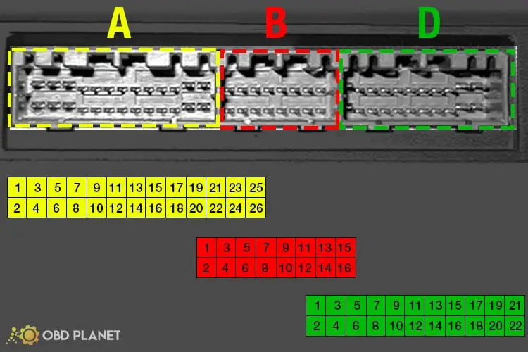

Connector A

| Pin number | Pin name | Description | Wire color |
|---|---|---|---|
| 1 | INJ1 | Injector 1 | Brown |
| 2 | INJ4 | Injector 4 | Yellow |
| 3 | INJ2 | Injector 2 | Red |
| 4 | VTS | VTEC solenoid | Orange/White |
| 5 | INJ3 | Injector 3 | Light blue |
| 6 | PO2SHTC | Primary O2 sensor heater control Civic VX D15Z1: HTCNTL (5-wire O2) | Orange/black |
| 7 | FLR | Fuel pump relay | Civic: Green/Yellow Integra: Green/Blue |
| 8 | Empty slot | -- | -- |
| 9 | IACV | Idle air control valve | Green/White |
| 10 | Empty slot | -- | -- |
| 11 | EGR | Exhaust gas recirculation solenoid valve Civic SOHC or ysed for H22/H23 EGR | Red or Orange/Blue |
| 12 | FANC | Radiator fan control | Yellow/Green |
| 13 | MIL | Malfunction indicator light | Green/Orange |
| 14 | Empty slot | -- | -- |
| 15 | ACC | A/C compressor clutch | Black/Red |
| 16 | ALTC | Alternator control | White/Green |
| 17 | IAB | Intake air bypass (Integra GSR B18C) | Pink |
| 18 | TCM | Transmission control module Empty slot for 5SPD Civic and Integra | |
| 19 | ICS | Intake control solenoid (H22A) Empty slot for Civic and Integra | White |
| 20 | PCS | Evap purge control solenoid valve | Red |
| 21 | ICM | Ignition control module | Red/Green |
| 22 | ICM | Ignition control module Note: Depin this when using an OBD1 AEM EMS | Red/Green |
| 23 | PG1 | Power ground | Black |
| 24 | PG2 | Power ground | Black |
| 25 | IGP2 | Power source | Yellow/Black |
| 26 | LG1 | Logic ground | Black/Red |
Connector B

| Pin number | Pin name | Description | Wire color |
|---|---|---|---|
| 1 | IGP1 | Power ground | Yellow/Black |
| 2 | LG2 | Logic ground | Brown/Black |
| 3 | TCM | Transmission control module Empty slot for 5SPD Civic and Integra | |
| 4 | TCM | Transmission control module Empty slot for 5SPD Civic and Integra | |
| 5 | ACS | A/C Switch signal | Blue/Red |
| 6 | Empty slot | -- | -- |
| 7 | M/T | Clutch switch (Civic VX only) Also used for A/T function | Pink/Black or Green (A/T) |
| 8 | PSPSW | P/S power switch signal Empty slot for Civic CX/DX/LX/EX/Si Empty slot for Integra | Red/Green |
| 9 | STS TMA/FAS | Starter signal switch Transmission related | STS - Civic: Blue/White - Integra: Blue/Red TMA/FAS - Civic: Grey - Integra: Yellow |
| 10 | VSS | Vehicle speed sensor | Yellow or Blue/Orange |
| 11 | CYP P | Cylinder position sensor side P (detection) | Orange |
| 12 | CYP M | Cylinder position sensor side M (ground) | White |
| 13 | TDC P | Top dead center sensor side PP(detection) | Orange/Blue |
| 14 | TDC M | Top dead center sensor side M (ground) | White/Blue |
| 15 | CKP P | Crankshaft position sensor side P (detection) | Blue/Yellow |
| 16 | CKP M | Crankshaft position sensor side M (ground) | Blue/Yellow |
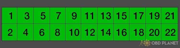
Connector D
| Pin number | Pin name | Description | Color |
|---|---|---|---|
| 1 | VBU | Voltage back up | White/Blue or White/Yellow |
| 2 | BKSW | Brake switch | Green/White |
| 3 | KS | Knock sensor Empty slot for Civic CX/DX/EX/Si Civic VX D15Z1: LAF sensor (5-wire O2) | Red/Blue |
| 4 | SCS | Service check signal | Civic: Brown Integra: Brown/White |
| 5 | Empty slot | -- | -- |
| 6 | VTPS/VTM | VTEC pressure switch | Orange/Blue or Light blue |
| 7 | TXD/RXD | Diagnostic data link | Light blue or Light green/Red |
| 8 | LAF sensor (5-wire O2) VS+ | Only Civic VX D15Z1, others are empty | -- |
| 9 | ALT FR | Alternator FR charge signal | Pink or White/Red |
| 10 | EL (ELD) | Electrical load detector | Green/Red or Green/Black |
| 11 | TPS | Throttle position sensor | Light green or Red/black |
| 12 | EGRL | EGR valve lift sensor (only Civic VX) | White/Black |
| 13 | ECT | Engine coolant temp sensor | Red/white or Yellow/Blue |
| 14 | PHO2 | Primary heated O2 Civic CX D15B8: 1-wire O2 Civic VX D15Z1: LAF sensor (5-wire O2) IP+ | White or White/Red |
| 15 | IAT | Intake air temp | Red/Yellow |
| 16 | LAF sensor (5-wire O2) IP-, VS- | Only Civic VX D15Z1 Empty slot for the others | Blue/Green |
| 17 | MAP | Manifold absolute pressure sensor | Civic: White Integra: White/Blue |
| 18 | Inter lock control unit | (A/T related) Civic CX/VX optional up-shift LT Empty slot for the others | White/Red Pink/Green |
| 19 | VCC1 | Sensor voltage for MAP | Civic: Yellow/Green Integra: Red/white |
| 20 | VCC2 | Sensor voltage for TPS | Yellow/White |
| 21 | SG1 | Sensor ground 1 | Civic: Green/Blue Integra: Blue/White |
| 22 | SG2 | Sensor ground 2 | Green/White |
GM OBD1 pinout
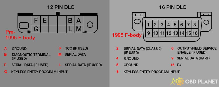
Ford OBD1 pinout
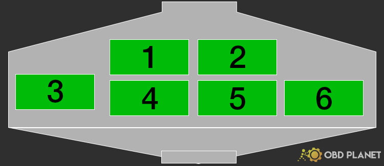
| Pin number | Description |
|---|---|
| 1 | Fuel pump enable output |
| 2 | Not used |
| 3 | Malfunction indictor lamp (MIL) output |
| 4 | K diagnostic line Data + |
| 5 | Data - |
| 6 | L diagnostic line Sensor signal return |