

Vehicles that were made in 1996 or later are all required by law to have an OBD2 system, which is a system that lets you or your mechanic communicate with the various electronic modules in your vehicle to obtain information and diagnose problems, and/or to ensure that everything is working as intended.
Each car contains a DLC (Data Link Connector) which allows a connection between the car’s ECU (Electronic Control Unit) and an OBD2 diagnostic scan tool. This is known as the OBD2 connector and is a 16-pin connector found in the area underneath the steering wheel in most vehicles.
A vehicle can have one of two OBD2 connector types, being Type A or Type B. Type A and Type B OBD2 connectors both have 16 connector pins, but differ slightly in terms of their shape, as illustrated further on in this article.
The OBD2 connector pinout (or pin layout) depends on the communication protocol used. There are five different OBD2 communication protocols, each of which are explained further below.
Let’s get to know about the five types of OBD2 protocols.

Types of OBD2 protocols
The five different OBD2 protocols are as follows:
- SAE J1850 PWM
- SEA J1850 VPW
- ISO 9141-2
- ISO 14230-4 (KWP2000)
- ISO 15765-4 (CAN) / SAE J2480
The most common protocol which is used by most vehicles on the road today is the ISO 15765-4 (CAN) protocol as this has been the mandatory protocol for OBD2 in all cars sold in the US since 2008.
However, before the ISO 15765-4 protocol was made mandatory in the US in 2008, there were four other protocols that were used, and if you currently have, or are working on a vehicle made before 2008, the vehicle may use one of the other four OBD2 protocols mentioned above.
Why is it important to know which protocol your vehicle uses? Well, while most OBD2 scan tools should work with most protocols, some protocols communicate better with certain scanners and may allow you to perform certain scans or tests that you wouldn’t be able to perform with a different scanner.
Below, you will find a bit more information on each of the five OBD2 protocols and also which makes and models of vehicles you are likely to find them in.
SAE J1850 PWM Protocol
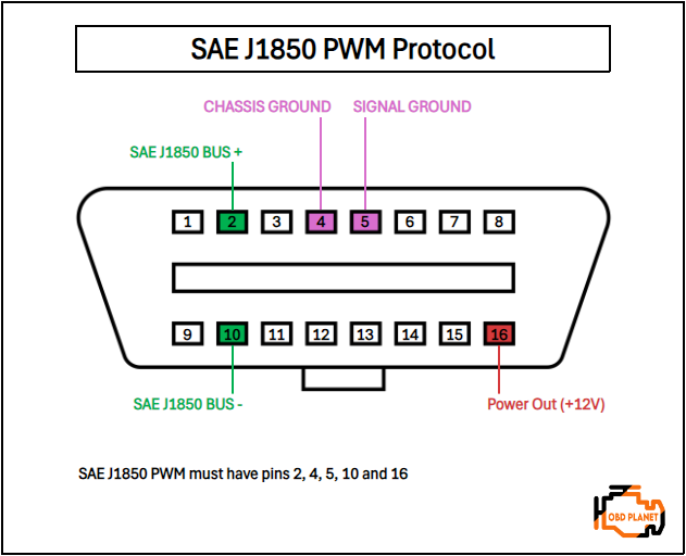
Connectors with a pinout including pins 2 and 10 are SAE J1850 PWM protocol. This protocol transfers data at 41.6 kb/sec and is mostly found in older Ford, Jaguar and Mazda vehicles. The signal produced by this protocol is called Pulse Width Modulation, hence the PWM in the protocol name.
Vehicles which use the SAE J1850 PWM protocol will always have a pinout including pins 2, 4, 5, 10, and 16.
SAE J1850 VPW Protocol
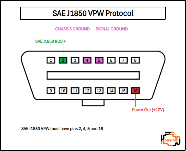
The SEA J1850 VPW protocol is generally found in older GM and Chrysler vehicles. This protocol transfers data at a speed of 10.4 kb/sec using Variable Pulse Width (VPW) signals.
Vehicles using the SAE J1850 VPW protocol will always have a pinout which includes pins 2, 4, 5, and 16. The easiest way to tell the difference between the VPW and PWM protocols is that vehicles using the VPW protocol have no pin 10.
ISO 9141-2 Protocol
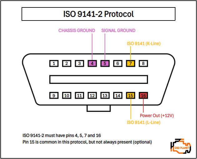
Next, the ISO 9141-2 protocol is another older protocol which is found in most European vehicles that were built between 2000 and 2004. You will also find this protocol on a number of Asian and Chrysler vehicles manufactured during this time period.
The data transfer speed of this protocol is 10.4 kb/sec and this protocol uses asynchronous serial communication, which is not as complex as the communication systems used by the J1850 standards.
Vehicles which use the ISO 9141-2 protocol will have a pinout that generally includes pins 4, 5, 7, 15 and 16. Vehicles using this protocol will always have pin 7, with pin 15 being optional. As usual, pins 4, 5 and 16 are must-haves in all protocols.
ISO 9141-2 protocol
Credit: youtube.com
ISO 14230-4 (KWP2000) Protocol
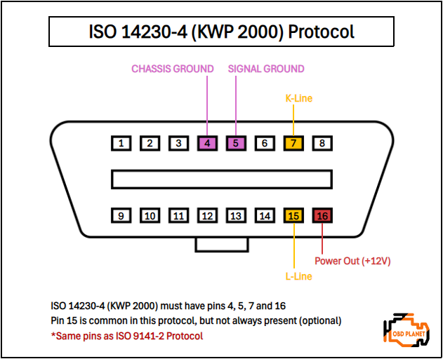
The ISO 14230-4 protocol (also known as the Keyword Protocol or KWP2000) also works on an asynchronous serial communication method that operates at 10.4 kb/sec.
The ISO 14230-4 protocol is found mostly in Asian manufactured vehicles which were manufactured from 2003 onwards.
The pinout on vehicles with the ISO 14230-4/KWP2000 protocol is identical to the ISO 9141-2 protocol. Vehicles which use the ISO 14230-4 protocol will have a pinout that generally includes pins 4, 5, 7, 15 and 16. Again, pin 7 (K-Line) will always be present, with pin 15 (L-Line) being optional.
Because it is similar to the ISO 9141-2 protocol (same pinout), you may have difficulty identifying this OBD2 protocol.
ISO 15765-4 (CAN) Protocol (SAE J2480)
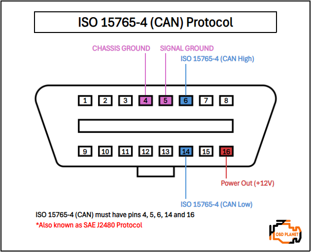
Lastly, the ISO 15765-4 (CAN) protocol (also known as SAE J2480) is the current standard and is found in the majority of modern cars and all US vehicles that were built in 2008 or later.
Vehicles using the ISO 15765-4 protocol will always have a pinout which includes pins 4, 5, 6, 14, and 16.
Furthermore, this OBD2 protocol has 4 variants:
- ISO 15765-4 CAN (250 Kbaud, 11 bit ID)
- ISO 15765-4 CAN (250 Kbaud, 29 bit ID)
- ISO 15765-4 CAN (500 Kbaud, 29 bit ID)
- ISO 15765-4 CAN (500 Kbaud, 11 bit ID)
It works on a two-wire communication method (pin 6 and 14) and is the highest speed protocol which can handle data transfer speeds of up to 1 Mbps.
What are the ways to check my OBD2 protocol?
OBD2 protocols: Must-have pins for the connector
| OBD2 Protocol | Pin 2 | Pin 6 | Pin 7 | Pin 10 | Pin 14 | Pin 15 |
|---|---|---|---|---|---|---|
| ISO 15765 CAN | ✔️ | ✔️ | ||||
| J1850 VPW | ✔️ | |||||
| ISO 9141 | ✔️ | ✔️ (Optional) | ||||
| J1850 PWM | ✔️ | ✔️ | ||||
| ISO 14230 KWP2000 | ✔️ | ✔️ (Optional) |
The easiest way to identify an OBD2 protocol is to look at the alignment and availability of the pins.
Here’s what you will need to focus on:
- If there are pins 2 and 10 in the connector, with metallic pins 2, 4, 5, 10 and 16 then the vehicle is using the SAE J1850 PWM protocol.
- If you can see pin 2 and material contacts inside pins 2, 4, 5, and 16 but there’s no pin 10 then the vehicle is using the SAE J1850 VPW protocol.
- If the connector has pin 7 and maybe pin 15 then the vehicle could be using either the ISO 9141-2 or ISO 14230-4 (KWP2000) protocol. The metallic contacts will be inside pins 4, 5, 7, 15 (*optional) and 16.
- If the vehicle has both pins 6 and 14 in its connector with material contacts 4, 5, 6, 14 and 16 then the vehicle is using the latest ISO 15765-4 (CAN) protocol.
Which OBD2 protocol is supported by my vehicle?
You will need to examine the OBD2 connector pins in the DLC in your vehicle using the guidelines above to determine which protocol is supported by your vehicle.
OBD2 Connector Types
As mentioned earlier in the article, there are two connector types, “Type A” and “Type B”.
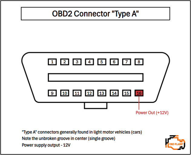
Type A: This type of OBD2 connector has the standard 16 pins altogether, with 8 pins on the upper row and 8 pins on the bottom row. Between the top and bottom rows of pins, there is a solid or uninterrupted groove (single groove) which signifies that it is a Type A connector.
Type A connectors are generally found in light motor vehicles (cars) and have a power output of 12V.
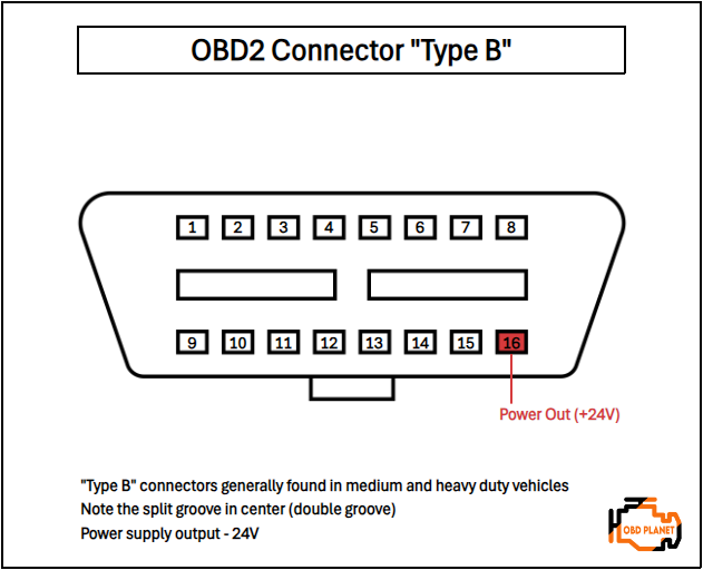
Type B: This OBD2 connector also has 16 pins (with 8 pins on the top and bottom rows) but it’s a bit different from the Type A connector. The difference with the Type B connector is that it has a split groove in the center (double groove) which restricts the Type A male connector from connecting to a Type B female socket. However, you will still be able to plug a Type B male connector into a Type A female socket as the double groove male connector will fit into the single groove female socket.
Type B connectors are generally found in medium and heavy duty vehicles and have a power output of 24V.
OBD2 Connector Pins Interpretation
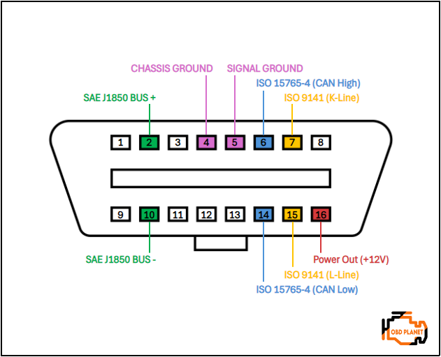
Since we know that Type A and Type B connectors both have 8 upper pins and 8 lower pins, let’s find out what each pin is meant for.
Pins on the upper row
- Pin 1: OEM COMM (Manufacturer specific).
- Pin 2: SAE J1850 Bus+.
- Pin 3: OEM Reserved/Discretionary (Manufacturer specific).
- Pin 4: Chassis ground.
- Pin 5: Signal ground.
- Pin 6: ISO 15765-4 (CAN High).
- Pin 7: K-Line.
- Pin 8: OEM Reserved/Discretionary (Manufacturer specific).
Pins on the lower row
- Pin 9: OEM COMM or Reserved/Discretionary (Manufacturer specific).
- Pin 10: SAE J1850 Bus- (SAE J1850 PWM only).
- Pin 11: OEM Reserved/Discretionary (Manufacturer specific).
- Pin 12: OEM Reserved/Discretionary (Manufacturer specific).
- Pin 13: OEM Reserved/Discretionary (Manufacturer specific).
- Pin 14: ISO 15765-4 (CAN Low).
- Pin 15: L-line.
- Pin 16: Power output (this pin powers the adapter).
Bottom line
We hope this information will help you identify your vehicle’s OBD2 protocol. It can be a bit difficult since they all look very similar or the same, but you will get it if you pay attention to the design and pins.
You may also like:
Best OBD2 scanners (from cheap to expensive) OBD2: The definitive guide to on-board diagnostics II
I bought an obd2 car diagnostic scanner elm 327 Bluetooth interface. It is not connecting with probox 2003 ECU though connecting with avirtz 2012 well . Advice.
Hi Charles,
Which product did you buy exactly? Also, ELM327 is compatible with practically all OBD2 cars that are made or sold in the US, so I think it won’t work properly on Probox 2003. My suggestion is to look for another ELM327 product.
I have a 1999 chevy silverado 1500 Canadian model.
it has pins 2,4,5,9,14, and 16, what protocal is it running?
Hi Jacob, it looks as though your vehicle is running on the SAE J1850 VPW protocol (not CAN / ISO 15765-4).
I understand some confusion may arise due to the fact that the vehicle has both pins 2 and 14, but in this case pin 2 is the SAE J1850 Bus + terminal and pin 14 is the E&C bus (not CAN Low / ISO 15765-4). The E&C bus is the Entertainment and Comfort serial bus which was used by GM roughly between 1987 and 2005 to allow for data transmission between the radio, CD changer, remote cassette player, HVAC system and OnStar module.
What would the typical power output be on the different busses if measured with a VOM? I get that you cant read data that way… Im just wondering what kind of volts/amps an OBD2 diagnostic tool is working with.
Hi Ernie, the power output depends on the type of vehicle. Light motor vehicles and trucks (cars, SUV’s, trucks etc.) all generally run on a 12V system, while heavier-duty vehicles (large trucks, busses etc.) use a 24V system.
The majority of OBD2 diagnostic tools run off 12V systems, although there are a few exceptions, with some diagnostic tools also being compatible with 24V systems so that they work on heavier-duty vehicles.
i have a 97 dodge dakota that i cannot read srs codes with different scanners. only has the obd2 port. looking for ideas for diagnosic tool for this antique
Hi Steve, please have a look at our article on the 10 Best SRS/Airbag scanners. Some of the scanners in the article that I believe should be compatible with your vehicle are the Autel MaxiLink ML619, the Autel MaxiLink ML629 and the Launch CR629.
You can also check our other articles on the Launch CRP123 range and Launch CRP129 range of scanners, which are also in the same sort of price range and which I believe should also be compatible with your vehicle.
I have a Toyota Hilux 2004 diesel 2KDFVM engine and these are the pins on the DLC 4, 5, 7, 9, 11, 12, 13, 15 and 16. However, two low cost scanners (Autel and Ancel) I purchased do not communicate using the OBD2.
I have now ordered an Autel MaxiCheck MX808S and am hoping this will work, as I would like to do some diagnostics on my truck. All advise and suggestions are welcome.
Thanks,
Hi Michael, sorry to hear you’ve had a poor experience with the scanners you’ve already tried out.
I know that the Hilux is very popular in South Africa, so if that’s where you are located, I may have some further bad news for you in that while the Autel MaxiCheck MX808S is a great scanner, most of the Japanese vehicles in South Africa are not OBD2 compliant due to the fact that its not law there as it is in Europe and the US. So, even the MX808S may not work for you sadly, but it’s definitely worth a shot.
If you’re really stuck, you can try an ELM327 adapter and a decent diagnostic software, such as TOAD Pro (Check out our article here), but again, there are unfortunately no guarantees.